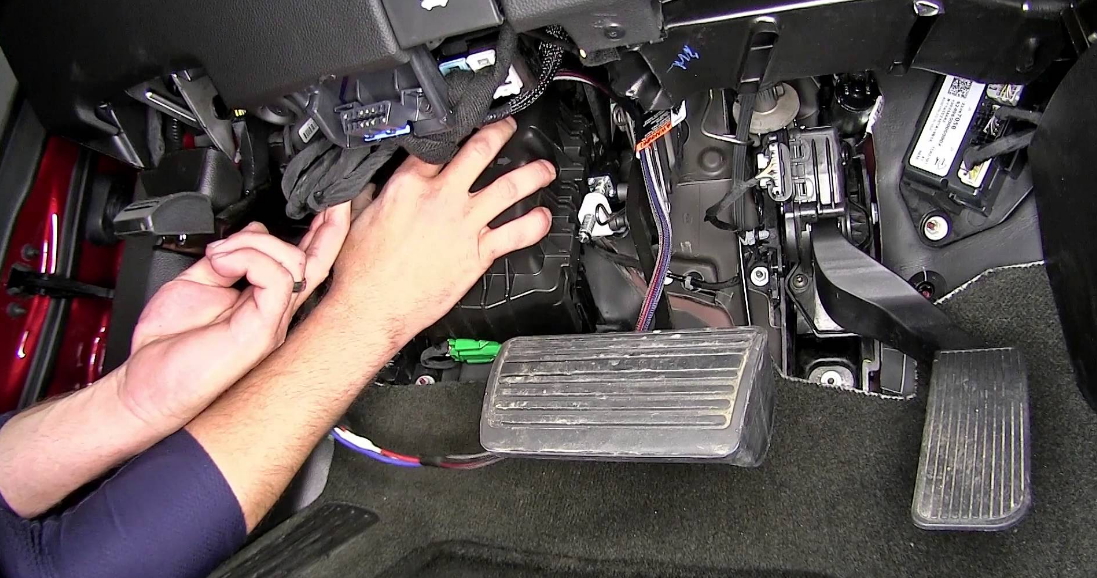
Brake Control Wiring Diagrams are essential tools for understanding the electrical systems in vehicles. These diagrams provide a detailed illustration of how the brake control system is wired, helping mechanics and technicians troubleshoot issues with the brakes.
Why are Brake Control Wiring Diagrams Essential?
- Help in understanding the electrical connections in the brake control system.
- Aid in troubleshooting brake control system issues.
- Enable proper installation of brake control components.
- Ensure safety by following correct wiring procedures.
How to Read and Interpret Brake Control Wiring Diagrams
When reading Brake Control Wiring Diagrams, it is important to understand the symbols and color codes used in the diagram. Each component is represented by a specific symbol, and the wires are color-coded to indicate their function. By following the lines and connections in the diagram, you can trace the flow of electricity through the brake control system.
Using Brake Control Wiring Diagrams for Troubleshooting
- Identify the components in the system and their connections.
- Check for continuity and proper voltage levels at various points in the wiring.
- Locate and repair any damaged or faulty wiring connections.
- Verify that all components are receiving power and functioning correctly.
Importance of Safety
Working with electrical systems can be dangerous if proper precautions are not taken. When using Brake Control Wiring Diagrams, it is important to follow safety guidelines to prevent accidents and injuries. Some safety tips to keep in mind include:
- Always disconnect the battery before working on the electrical system.
- Use insulated tools to avoid electrical shock.
- Avoid working on the wiring when the system is powered on.
- Double-check all connections before re-energizing the system.
Brake Control Wiring Diagram
duramax TRAILER BRAKE CONTROL WIRING SCHEMATICS User Manual

How do I install trailer brake wiring for jeep grand cherokee

Curt Discovery Brake Control Wiring Diagram

Wiring Diagram Brake Controller

How to Install a Brake Controller

Electric Brake Controller Complete with Leader Cable to Wire to Trailer

Tekonsha P3 Prodigy Electric Trailer Brake Controller Wiring Diagram

Hopkins Agility Brake Controller Wiring Diagram For 2007 Dodge Ram 1500
