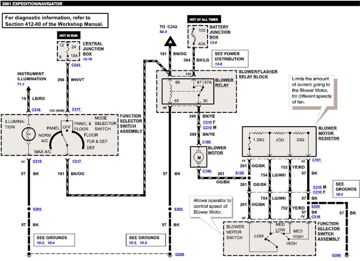
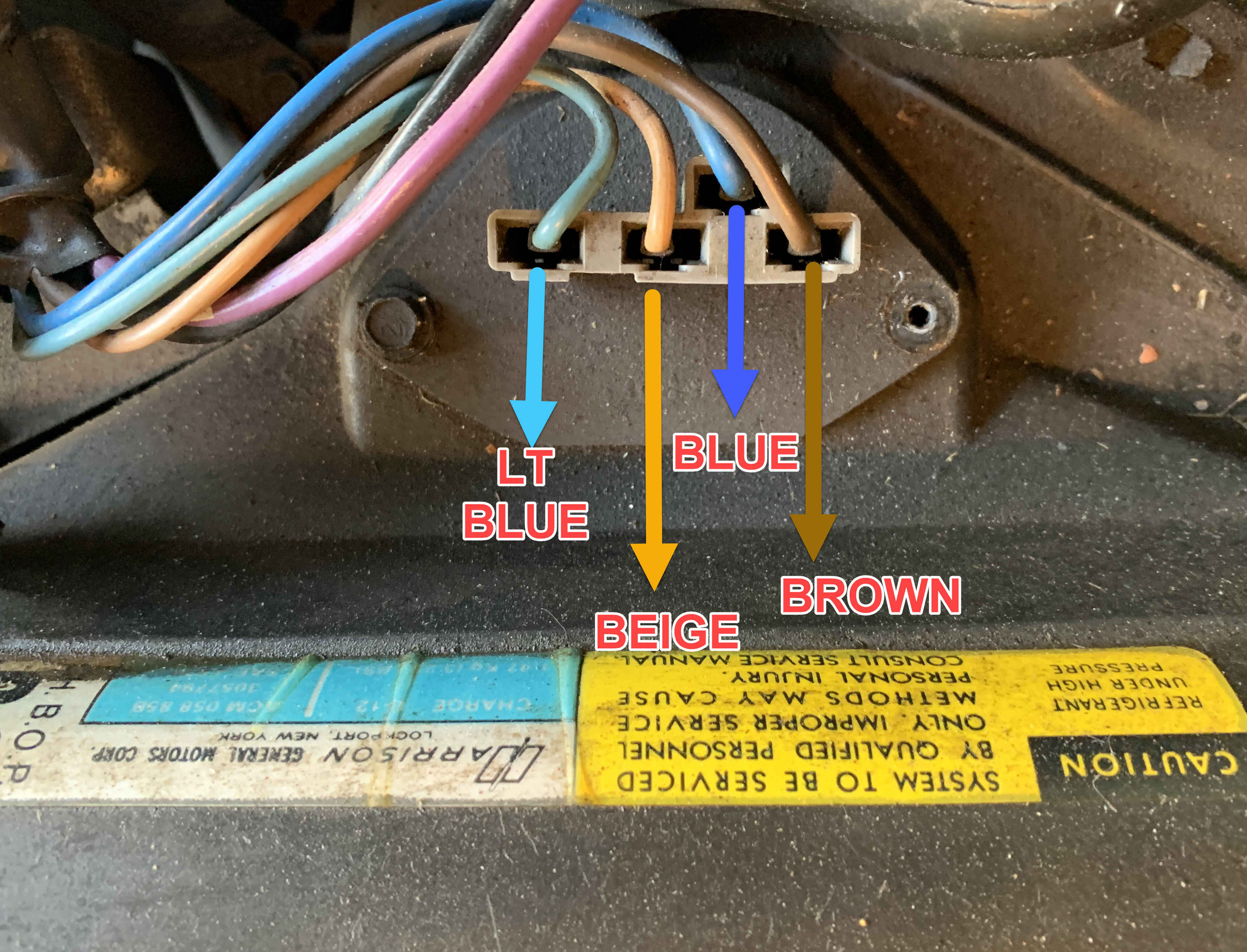
When it comes to understanding the inner workings of your vehicle’s HVAC system, a Blower Motor Wiring Diagram is an essential tool. This diagram provides a visual representation of how the blower motor is wired within the system, allowing you to troubleshoot any electrical issues that may arise.
Importance of Blower Motor Wiring Diagrams
Blower Motor Wiring Diagrams are crucial for several reasons:
- They help you understand the wiring configuration of the blower motor, ensuring proper installation and operation.
- They can assist in diagnosing electrical problems within the HVAC system.
- They serve as a reference guide for maintenance and repairs.
- The color coding of wires to ensure proper connections.
- The symbols used to represent different components in the system.
- The direction of current flow indicated by arrows.
- Always disconnect the power source before working on the electrical system.
- Use insulated tools to prevent electric shock.
- Avoid working on the system in wet or damp conditions.
- If you’re unsure about a particular wiring diagram, seek the assistance of a professional mechanic.
Reading and Interpreting Blower Motor Wiring Diagrams
When reading a Blower Motor Wiring Diagram, it’s important to pay attention to the following:
Using Blower Motor Wiring Diagrams for Troubleshooting
Blower Motor Wiring Diagrams can be invaluable when troubleshooting electrical problems in your vehicle’s HVAC system. By following the wiring diagram and checking for continuity, you can pinpoint issues such as faulty connections, broken wires, or malfunctioning components.
It’s important to approach troubleshooting systematically, starting with the power source and working your way through the wiring diagram to identify any discrepancies. This methodical approach can save time and prevent unnecessary repairs.
Safety Considerations
Working with electrical systems can be dangerous, so it’s crucial to follow safety precautions when using Blower Motor Wiring Diagrams:
Blower Motor Wiring Diagram
Sentra Blower Motor Wiring Diagram – Diagramming Tale

Automotive Blower Motor Wiring Diagram

Wiring A Blower Motor

Blower Motor Wiring Diagram

Blower Motor Wiring

Mars Direct Drive Blower Motor Wiring Diagram – Wiring Diagram Pictures

How to Replace an Automotive Blower Motor Fan

4 Speed Motor Wiring Diagram, 82 – 87 Monte Carlo Blower Motor Speed
