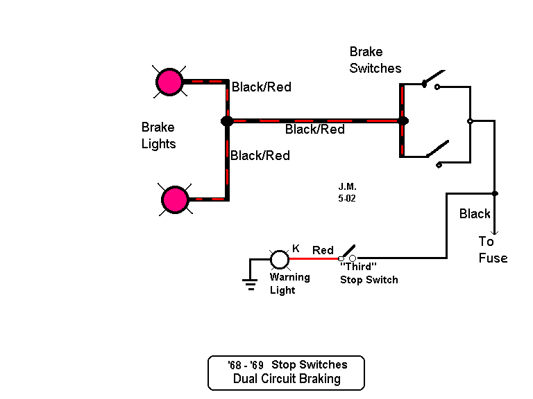
Basic Brake Light Switch Wiring Diagrams are essential diagrams that show the wiring layout of the brake light switch in a vehicle. These diagrams are crucial for understanding how the brake light circuit works and for troubleshooting any issues that may arise with the brake lights.
Importance of Basic Brake Light Switch Wiring Diagrams
Understanding Basic Brake Light Switch Wiring Diagrams is important for the following reasons:
- Ensuring proper functioning of the brake lights
- Troubleshooting electrical issues related to the brake lights
- Helping in the installation of new brake light switches
Reading and Interpreting Basic Brake Light Switch Wiring Diagrams
When reading Basic Brake Light Switch Wiring Diagrams, it is important to:
- Understand the symbols and colors used in the diagram
- Follow the flow of the wiring from the brake light switch to the brake lights
- Identify any relays or fuses that may be included in the circuit
Using Basic Brake Light Switch Wiring Diagrams for Troubleshooting
Basic Brake Light Switch Wiring Diagrams can be used for troubleshooting electrical problems by:
- Checking for continuity in the wiring using a multimeter
- Identifying any loose connections or damaged wires
- Testing the brake light switch for proper functionality
Safety Tips for Working with Basic Brake Light Switch Wiring Diagrams
When working with electrical systems and using wiring diagrams, it is important to prioritize safety. Here are some safety tips and best practices to follow:
- Always disconnect the battery before working on any electrical components
- Use insulated tools to prevent electrical shocks
- Avoid working on electrical systems in wet or damp conditions
- Refer to the vehicle’s service manual for specific safety precautions
Basic Brake Light Switch Wiring Diagram
Basic Brake Light Switch Wiring Diagram
Brake Light Wiring Schematic

Brake Light Circuit Diagram

Trailer Brake Light Wiring

Motorcycle Brake Light Switch Wiring Diagram – Fab Saga

Hydraulic Brake Light Switch Wiring

How To Wire A Brake Light Switch | Homeminimalisite.com

Brake Light Wiring Diagram
