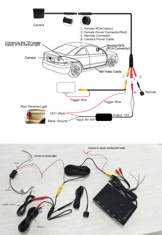
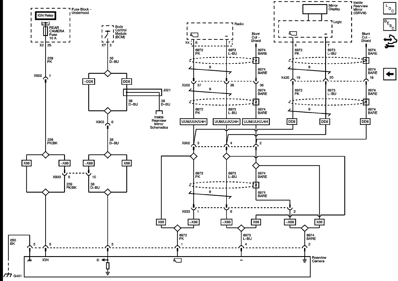
When it comes to installing or repairing a back-up camera system in a vehicle, having a clear understanding of the wiring diagram is crucial. A back-up camera wiring diagram provides a visual representation of the electrical connections and components involved in the system, helping you to effectively install, troubleshoot, and maintain the camera.
Why Back Up Camera Wiring Diagrams are Essential
Back up camera wiring diagrams are essential for several reasons:
- They provide a clear visual guide for connecting the camera to the vehicle’s electrical system.
- They help ensure that the camera is installed correctly, preventing damage to the camera or the vehicle.
- They assist in troubleshooting electrical issues that may arise during installation or use of the camera.
Reading and Interpreting Back Up Camera Wiring Diagrams
When reading a back up camera wiring diagram, it’s important to pay attention to the following:
- The color codes for wires, which indicate the function of each wire (e.g., power, ground, video signal).
- The symbols used to represent different components (e.g., camera, monitor, control module).
- The connections between components, including where each wire should be connected.
Using Back Up Camera Wiring Diagrams for Troubleshooting
Back up camera wiring diagrams can be invaluable for troubleshooting electrical problems. By following the diagram and checking the connections between components, you can easily identify and fix issues such as loose connections, damaged wires, or faulty components. The wiring diagram serves as a roadmap for diagnosing and resolving electrical issues effectively.
Importance of Safety
Working with electrical systems, including back up camera wiring, requires caution and attention to safety. To ensure your safety and the safety of your vehicle, consider the following tips:
- Always disconnect the vehicle’s battery before working on the electrical system.
- Avoid working on the wiring when the vehicle is running or the key is in the ignition.
- Use insulated tools to prevent electrical shock.
- Double-check your connections before testing the system to avoid short circuits or damage.
Back Up Camera Wiring Diagram
Component Diagram – Install Instructions – Page 5 – Anytime Backup Camera

Universal Mount Backup Camera (Front/Reverse Camera) – J&T Distributing

Wiring A Backup Camera Diagram

Backup Camera Wiring Diagram Look Right

Box Camera Wiring Diagram

2015 Gmc 3500 Flatbed Backup Camera Wiring Diagram

Rv Backup Camera Wiring Diagram – Loom Fit

️Boss Backup Camera Wiring Diagram Free Download| Gmbar.co
