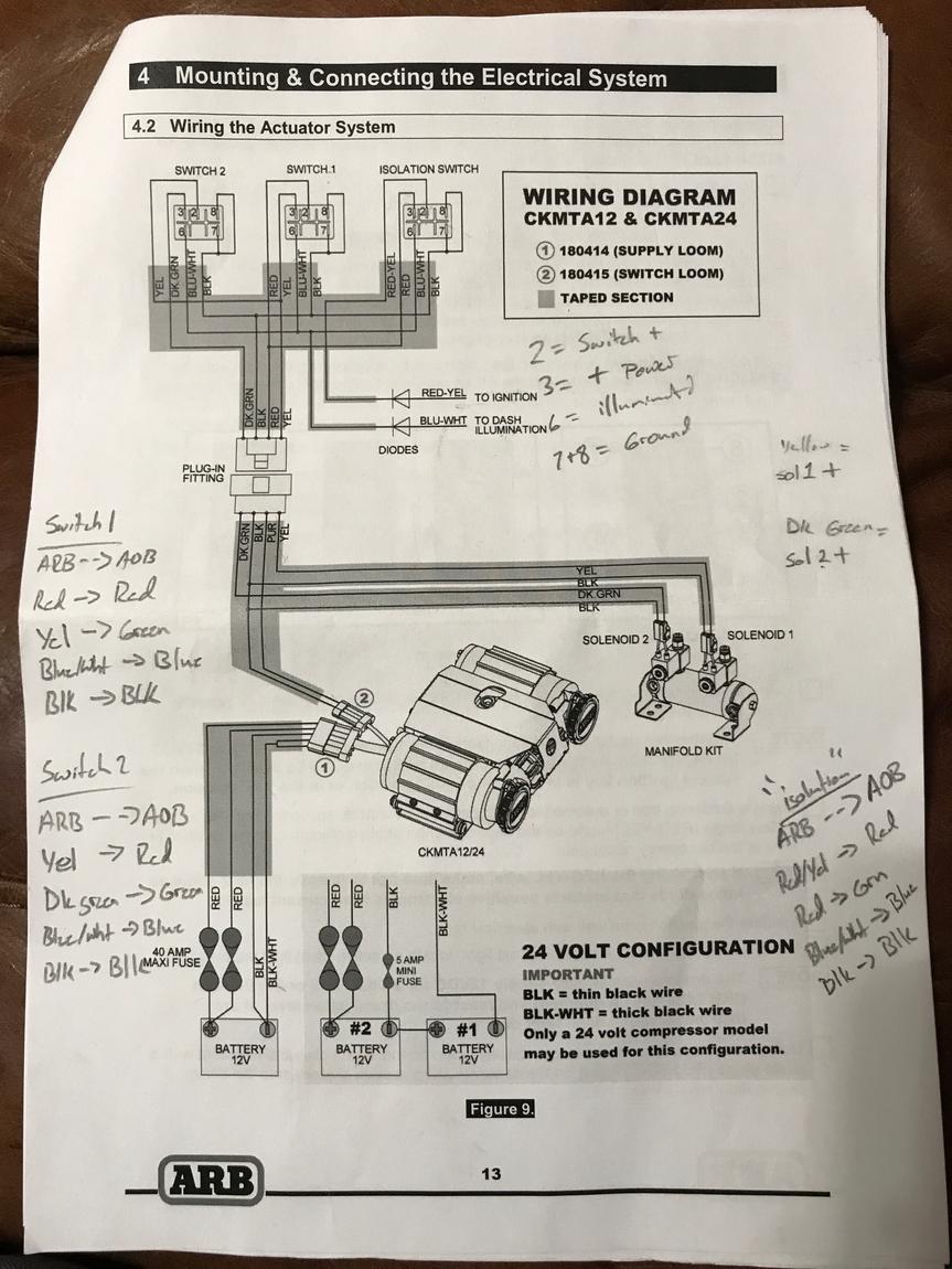
Arb Air Compressor Wiring Diagrams are essential tools for understanding and troubleshooting the electrical systems of air compressors. These diagrams provide a visual representation of the wiring connections and components within the compressor, making it easier to identify and resolve any electrical issues.
Why Are Arb Air Compressor Wiring Diagrams Essential?
- Help in understanding the electrical layout of the compressor
- Aid in troubleshooting electrical problems
- Ensure proper installation and maintenance
- Prevent electrical hazards and accidents
How to Read and Interpret Arb Air Compressor Wiring Diagrams
Arb Air Compressor Wiring Diagrams can appear complex at first glance, but with some guidance, they can be easily understood and utilized effectively.
- Start by identifying the main components of the compressor on the diagram
- Follow the lines to trace the wiring connections between components
- Refer to the legend or key for symbols and color codes used in the diagram
- Pay attention to labels and annotations for additional information
Using Arb Air Compressor Wiring Diagrams for Troubleshooting
Arb Air Compressor Wiring Diagrams are invaluable for diagnosing and resolving electrical problems within the compressor.
- Use the diagram to trace the flow of electricity and identify any loose connections or faulty components
- Compare the diagram with the actual wiring to check for discrepancies or defects
- Refer to the troubleshooting section of the manual for specific issues and solutions
Importance of Safety When Working with Arb Air Compressor Wiring Diagrams
When using Arb Air Compressor Wiring Diagrams, it is crucial to prioritize safety to prevent accidents and injuries.
- Always disconnect the power source before working on the electrical system
- Wear appropriate protective gear, such as gloves and safety goggles
- Follow proper procedures and guidelines outlined in the manual
- If unsure or inexperienced, seek assistance from a professional mechanic or electrician
Arb Air Compressor Wiring Diagram
Arb Single Air Compressor Wiring Diagram – Wiring Digital and Schematic
Arb Compressor Switch Wiring

Arb Compressor Wiring Diagram
Arb Onboard Air Compressor Wiring Diagram – Wiring Diagram Pictures

ARB Compressor Wiring | Bronco6G – 2021+ Ford Bronco & Bronco Raptor
Arb Compressor Switch Wiring Diagram – Diariesid

ARB Dual Compressor Simple Wiring – YouTube

Arb Air Compressor Wiring Diagram For Your Needs
