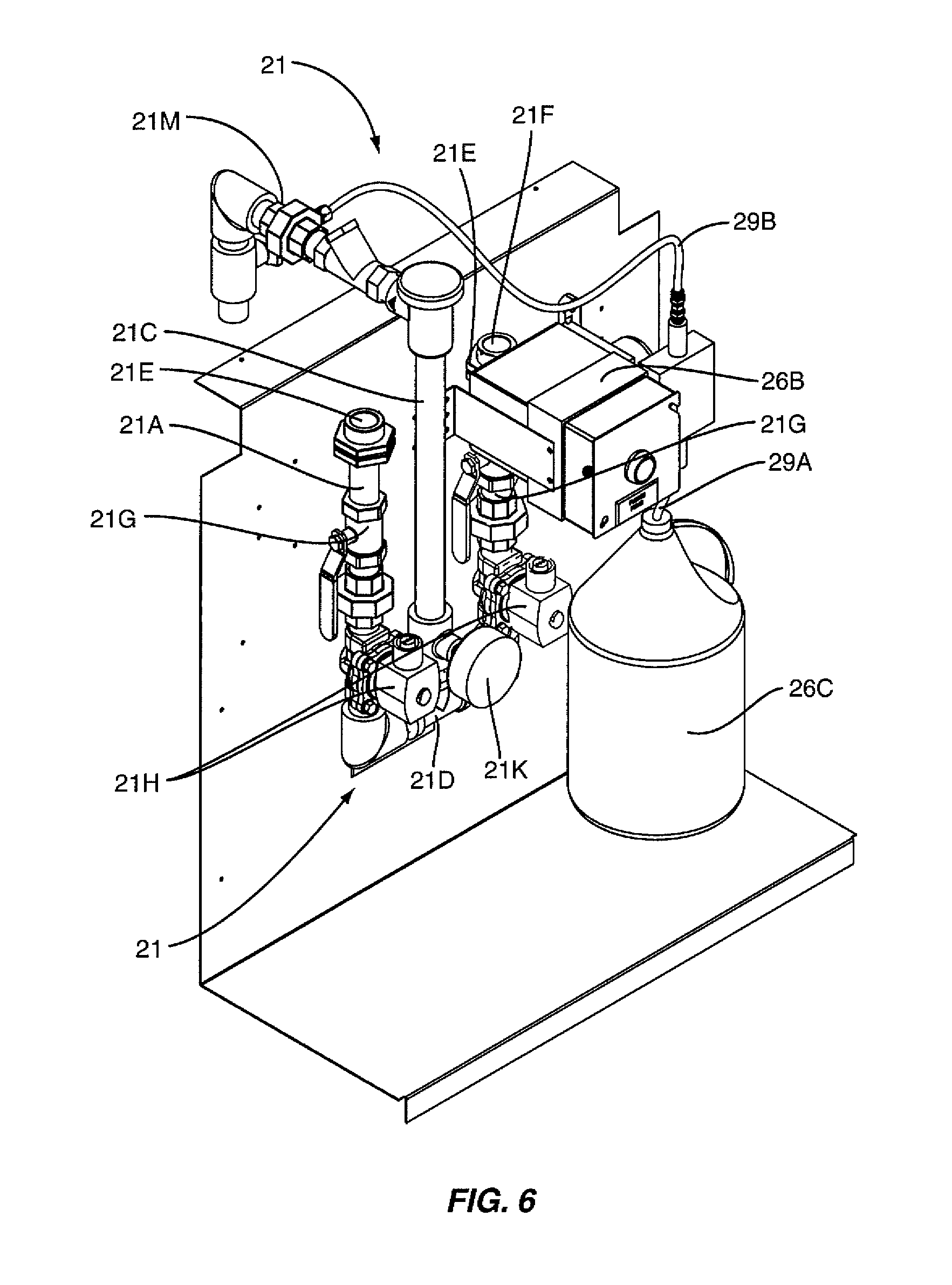
When it comes to ensuring the safety and functionality of electrical systems, understanding the Ansul Micro Switch Wiring Diagram is crucial. This diagram provides a detailed overview of how the micro switch is wired within the Ansul system, allowing for easy troubleshooting and maintenance.
Importance of Ansul Micro Switch Wiring Diagram
- Ensures proper installation of the micro switch within the Ansul system
- Aids in troubleshooting electrical issues quickly and efficiently
- Provides a clear visual representation of the wiring configuration
- Helps prevent potential hazards or accidents due to incorrect wiring
Reading and Interpreting Ansul Micro Switch Wiring Diagram
When looking at an Ansul Micro Switch Wiring Diagram, it’s important to pay attention to the following:
- Identify the components and their corresponding symbols
- Follow the wiring paths to understand the connections between components
- Note any labels or descriptions that indicate the function of each part
Using Ansul Micro Switch Wiring Diagram for Troubleshooting
When facing electrical problems within the Ansul system, the wiring diagram can be a valuable tool for troubleshooting. Here’s how you can use it effectively:
- Trace the wiring to identify any loose connections or damaged components
- Check for continuity using a multimeter to ensure proper electrical flow
- Compare the actual wiring to the diagram to pinpoint any discrepancies
Safety Tips for Working with Ansul Micro Switch Wiring Diagram
Working with electrical systems can pose various risks, so it’s crucial to prioritize safety. Here are some tips to keep in mind:
- Always turn off the power supply before working on any electrical components
- Use insulated tools to prevent electrical shocks
- Avoid working on live circuits whenever possible
- Double-check your work and consult the wiring diagram to ensure accuracy
Ansul Micro Switch Wiring Diagram
Ansul Micro Switch Wiring Diagram

Skill Wiring: Ansul Micro Switch Wiring Diagram

Ansul Micro Switch Wiring Diagram – Greenic
Worksful: Ansul Micro Switch Wiring Diagram

ansul micro switch wiring diagram – MaddixRidhay

Ansul Micro Switch Wiring Diagram

Ansul Micro Switch Wiring Diagram – Greenic
ansul micro switch wiring diagram – MaddixRidhay
