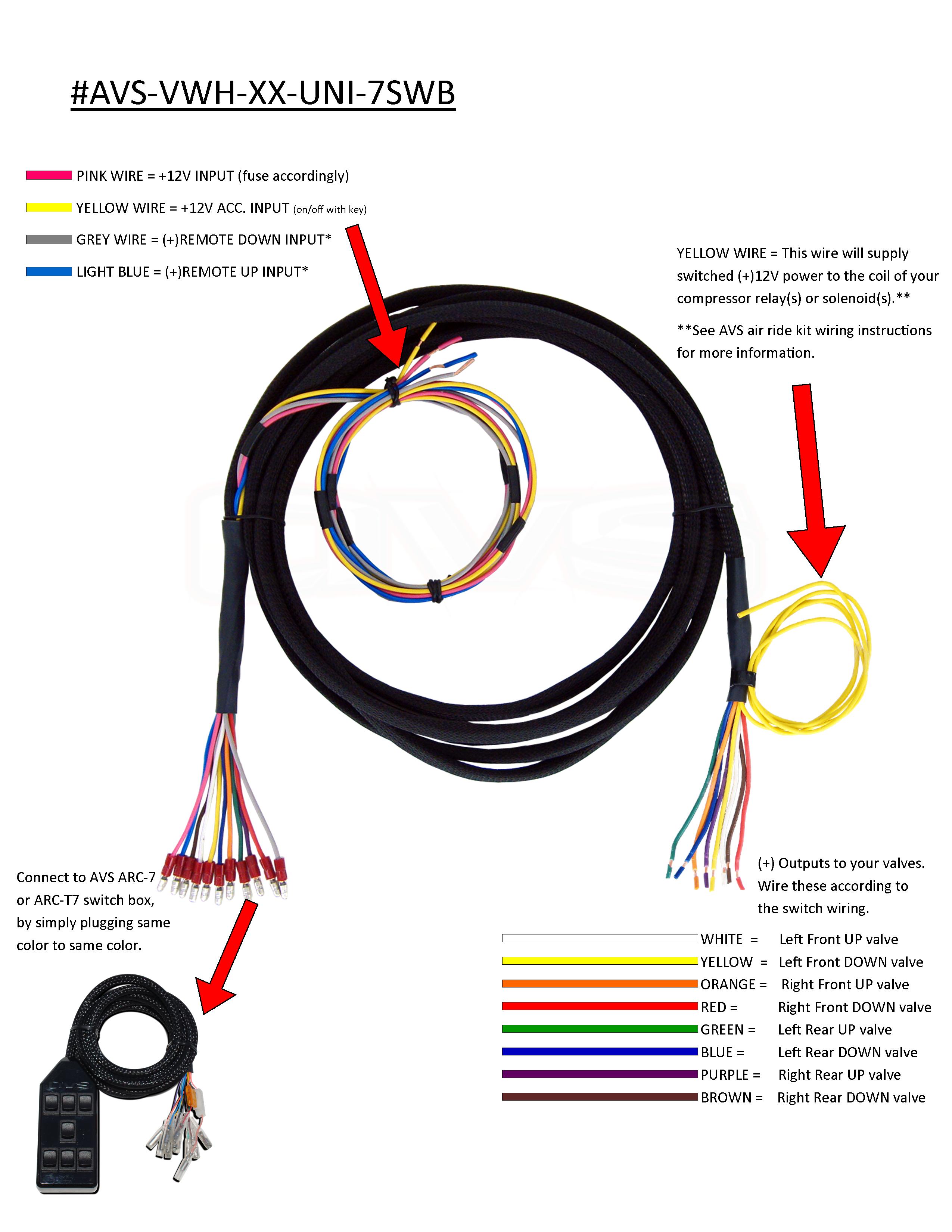
When working on your vehicle’s air ride system, understanding the Air Ride Switch Box Wiring Diagram is crucial for proper installation and troubleshooting. This diagram provides a visual representation of how the various components are connected and powered within the system.
Importance of Air Ride Switch Box Wiring Diagram
- Ensures proper installation of the air ride system components
- Aids in troubleshooting electrical issues
- Helps prevent damage to the system due to incorrect wiring
Reading and Interpreting Air Ride Switch Box Wiring Diagram
When looking at the diagram, it is important to understand the symbols and color codes used to represent different components and connections. Pay close attention to the key provided with the diagram to accurately interpret the information.
Using Air Ride Switch Box Wiring Diagram for Troubleshooting
When facing electrical problems with your air ride system, refer to the wiring diagram to identify possible issues such as loose connections, damaged wires, or faulty components. By following the diagram, you can systematically check and test each part of the system to pinpoint the source of the problem.
Safety Tips for Working with Air Ride Switch Box Wiring Diagram
- Always disconnect the power source before working on the electrical system
- Use insulated tools to prevent electrical shocks
- Avoid working on the system in wet or damp conditions
- Double-check all connections and wiring before reapplying power to the system
Air Ride Switch Box Wiring Diagram
Air Ride Switch Box Wiring Diagram

[DIAGRAM] 10 Air Ride Switch Box Wiring Diagram – MYDIAGRAM.ONLINE
![Air Ride Switch Box Wiring Diagram [DIAGRAM] 10 Air Ride Switch Box Wiring Diagram - MYDIAGRAM.ONLINE](https://i1.wp.com/cdn.shopify.com/s/files/1/1025/4963/files/PRINT-DUAL-COMPRESSOR-WIRING-2017.jpg?13633902248154252169)
Air Ride Technologies Wiring Diagram

Easy Street Air Ride Wiring Diagram

Air Ride Switch Box Wiring Diagram – Wiring Diagram Database
air ride switch box wiring diagram – JedwigaRomy

️Air Ride Compressor Wiring Diagram Free Download| Gmbar.co

Avs 3 Switch Box Wiring Diagram – Wiring Diagram
