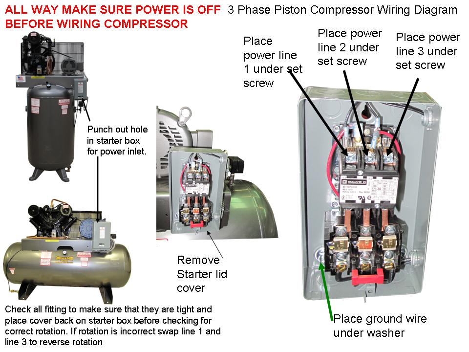
Air Compressor Electrical Wiring Diagram
An Air Compressor Electrical Wiring Diagram is a visual representation of the electrical connections and circuitry of an air compressor. It shows how the various components of the compressor are connected and powered, allowing technicians to understand and troubleshoot the electrical system.
Why are Air Compressor Electrical Wiring Diagrams Essential?
Understanding Air Compressor Electrical Wiring Diagrams is essential for several reasons:
- Ensures proper installation of the air compressor
- Aids in troubleshooting electrical issues
- Helps in performing maintenance and repairs
How to Read and Interpret Air Compressor Electrical Wiring Diagrams
Reading and interpreting Air Compressor Electrical Wiring Diagrams can be daunting for some, but with a bit of practice, it becomes easier. Here are some tips:
- Identify the components and their symbols
- Follow the flow of the electrical circuitry
- Understand the connections and wiring color codes
Using Air Compressor Electrical Wiring Diagrams for Troubleshooting
Air Compressor Electrical Wiring Diagrams are invaluable when troubleshooting electrical problems. By following the wiring diagram, technicians can:
- Locate faulty components or connections
- Test for continuity and voltage at various points
- Isolate and resolve electrical issues effectively
Safety Tips when Working with Electrical Systems
When working with Air Compressor Electrical Wiring Diagrams, it is crucial to prioritize safety. Here are some safety tips and best practices to follow:
- Always disconnect power before working on the electrical system
- Use insulated tools to prevent electrical shocks
- Wear appropriate personal protective equipment (PPE)
- Follow manufacturer’s guidelines and local electrical codes
Air Compressor Electrical Wiring Diagram
Compressor Wiring Diagram – Worksic

How to make air compressor wiring diagram 3 phase | portable air

Compressor Wiring Diagram – Worksic

Ingersoll Rand T30 Air Compressor Wiring Diagram – Wiring Diagram and
Basic Air Conditionerpressor Wiring Diagram

Ingersoll Rand T30 Air Compressor Wiring Diagram – Wiring Diagram and
Air Conditioning Compressor Wiring Diagram

Kobalt 80 Gallon Air Compressor Wiring Diagram – Wiring Diagram
