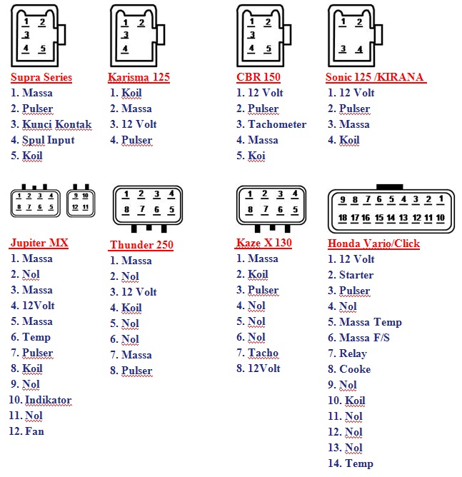
7 Pin Cdi Wiring Diagram is a crucial tool in the world of automotive maintenance and repair. It provides a detailed schematic of the electrical connections in a vehicle’s ignition system, helping mechanics and technicians troubleshoot issues and make necessary repairs.
Why are 7 Pin Cdi Wiring Diagrams Essential?
- Helps identify the location of each wire and its corresponding component
- Ensures proper installation of new components
- Aids in diagnosing electrical problems quickly and accurately
- Serves as a reference guide for future maintenance and repairs
How to Read and Interpret 7 Pin Cdi Wiring Diagrams Effectively
Reading and interpreting 7 Pin Cdi Wiring Diagrams may seem daunting at first, but with some practice and understanding, it becomes a valuable skill. Here are some tips to help you navigate through the diagram effectively:
- Start by identifying the key components, such as the ignition coil, spark plug, and CDI unit
- Follow the flow of the diagram from the power source to the various components
- Pay attention to the color codes and symbols used in the diagram
- Refer to the legend or key if you are unsure about any symbol or abbreviation
Using 7 Pin Cdi Wiring Diagrams for Troubleshooting Electrical Problems
When faced with electrical issues in a vehicle, a 7 Pin Cdi Wiring Diagram can be a lifesaver. Here’s how you can use the diagram for troubleshooting:
- Trace the wiring to identify any loose connections or damaged wires
- Check for continuity using a multimeter to ensure the electrical flow is intact
- Compare the actual wiring in the vehicle with the diagram to spot any discrepancies
- Use the diagram to pinpoint the source of the problem and make necessary repairs
It is crucial to prioritize safety when working with electrical systems and using wiring diagrams. Here are some safety tips and best practices to keep in mind:
- Always disconnect the battery before working on any electrical components
- Avoid working on wet or damp surfaces to prevent electrical shock
- Use insulated tools and wear appropriate protective gear, such as gloves and safety glasses
- Double-check your work and ensure all connections are secure before reassembling the vehicle
7 Pin Cdi Wiring Diagram
[DIAGRAM] 7 Wire Cdi Diagram – MYDIAGRAM.ONLINE
![7 Pin Cdi Wiring Diagram [DIAGRAM] 7 Wire Cdi Diagram - MYDIAGRAM.ONLINE](https://i1.wp.com/images-na.ssl-images-amazon.com/images/I/81trvDCbUQL._AC_SL1500_.jpg)
7 Wire Cdi Box Diagram – Wiring Diagram Networks
7 pin cdi wiring diagram – LilliasKahlen

Cdi Box Wiring Diagram

7 Wire Cdi Box Wiring Diagram

Connection pin CDI | Motor Cycle

Isla Wiring: Honda Cdi Box Wiring Diagram Pictures

Connection pin CDI | Motor Cycle
