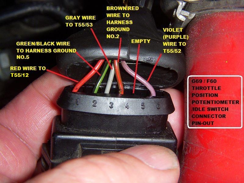
Are you looking for information on 6 Pin Throttle Position Sensor Wiring Diagram? Understanding how to read and interpret these diagrams is crucial for any mechanic or DIY enthusiast working on electrical systems in vehicles. Let’s delve into the details of these diagrams and how they can be used effectively.
Why are 6 Pin Throttle Position Sensor Wiring Diagrams Essential?
6 Pin Throttle Position Sensor Wiring Diagrams are essential for understanding the electrical connections and signals within a vehicle’s throttle position sensor. These diagrams provide a visual representation of the wiring layout, pin configurations, and connection points, making it easier to diagnose and troubleshoot any issues that may arise.
How to Read and Interpret 6 Pin Throttle Position Sensor Wiring Diagrams
Reading and interpreting 6 Pin Throttle Position Sensor Wiring Diagrams may seem daunting at first, but with some guidance, it can be a straightforward process. Here are some tips to help you navigate these diagrams effectively:
- Identify the pins and their corresponding functions
- Follow the wiring paths and connections
- Understand the color-coding and symbols used in the diagram
- Pay attention to the legend or key for additional information
Using 6 Pin Throttle Position Sensor Wiring Diagrams for Troubleshooting Electrical Problems
6 Pin Throttle Position Sensor Wiring Diagrams can be invaluable tools when troubleshooting electrical problems in a vehicle. By following the wiring diagram and tracing the connections, you can pinpoint any issues with the sensor, wiring harness, or related components. This can save time and effort in diagnosing and resolving electrical issues effectively.
Importance of Safety When Working with Electrical Systems
When working with electrical systems and using wiring diagrams, safety should always be a top priority. Here are some safety tips and best practices to keep in mind:
- Always disconnect the battery before working on any electrical components
- Use insulated tools to prevent electrical shocks
- Avoid working on electrical systems in wet or damp conditions
- Double-check connections and wiring before testing or powering up the system
6 Pin Throttle Position Sensor Wiring Diagram
Dodge Ram Throttle Body Wiring: Q&A on 6-Pin Throttle Position Sensor

Ford Tps Wiring Diagram

6 Pin Throttle Position Sensor Wiring Diagram | Wiring Expert Group

Tps wiring issue – S2Forum – The Audi S2 Community

Understanding 6 Pin Throttle Position Sensor Wiring Diagrams – Wiring

Ford Throttle Position Sensor Wiring Diagram – Artsian

6 Pin Throttle Position Sensor Wiring Diagram – Wiring Service

Qs Motor Throttle Wiring Diagram
