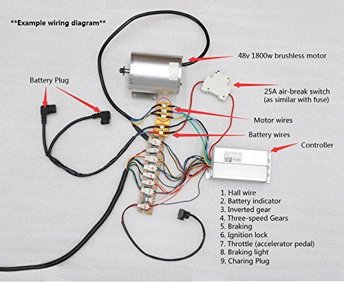
When it comes to understanding the intricacies of electrical systems in vehicles or machinery, having a clear and detailed 48v Brushless Motor Controller Wiring Diagram is essential. This diagram serves as a roadmap for technicians and mechanics to properly connect and troubleshoot the wiring of a 48v brushless motor controller.
Importance of 48v Brushless Motor Controller Wiring Diagram
Having a 48v Brushless Motor Controller Wiring Diagram is crucial for several reasons:
- Ensures proper installation of the motor controller
- Facilitates troubleshooting of electrical issues
- Helps prevent short circuits or incorrect connections
Reading and Interpreting 48v Brushless Motor Controller Wiring Diagram
Reading and interpreting a 48v Brushless Motor Controller Wiring Diagram may seem daunting at first, but with some guidance, it can be a valuable tool:
- Identify the components: Understand the symbols and labels used in the diagram
- Follow the flow: Trace the wiring from start to finish to understand the circuit layout
- Check for color codes: Pay attention to color-coded wires for easy identification
Using 48v Brushless Motor Controller Wiring Diagram for Troubleshooting
When faced with electrical problems, a 48v Brushless Motor Controller Wiring Diagram can be your best friend:
- Locate the issue: Use the diagram to pinpoint where the problem might be occurring
- Check for continuity: Test the wiring connections to ensure proper continuity
- Follow the circuit: Trace the circuit to find any loose connections or damaged components
Safety Tips for Working with Electrical Systems
Working with electrical systems can be dangerous, so it’s important to prioritize safety:
- Always disconnect the power source before working on any electrical components
- Use insulated tools to prevent electrical shocks
- Avoid working on electrical systems in wet or damp conditions
- Double-check all connections before powering up the system
48v Brushless Motor Controller Wiring Diagram
[DIAGRAM] 48v Electric Bike Controller Wiring Diagram – WIRINGDIAGRAM
![48v Brushless Motor Controller Wiring Diagram [DIAGRAM] 48v Electric Bike Controller Wiring Diagram - WIRINGDIAGRAM](https://i1.wp.com/diagramweb.net/img/48v-brushless-motor-controller-wiring-diagram-9.jpg)
TDPRO 48V 1800W Electric Bicycle Brushless Speed Motor Controller for

Ebike 1000w 48v Controller Wiring Diagram

Brushless Motor Controller Wiring Diagram

48v Brushless Motor Controller Wiring Diagram

Brushless Dc Motor Controller Wiring Diagram

GREENTIME 36V/48V 500W/600W 30Amax BLDC Motor Controller Electric Bike
Brushless motors, BLDC Motor, Sensorless Motor, Motor Controllers, FOC
