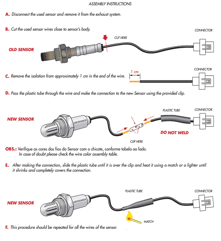
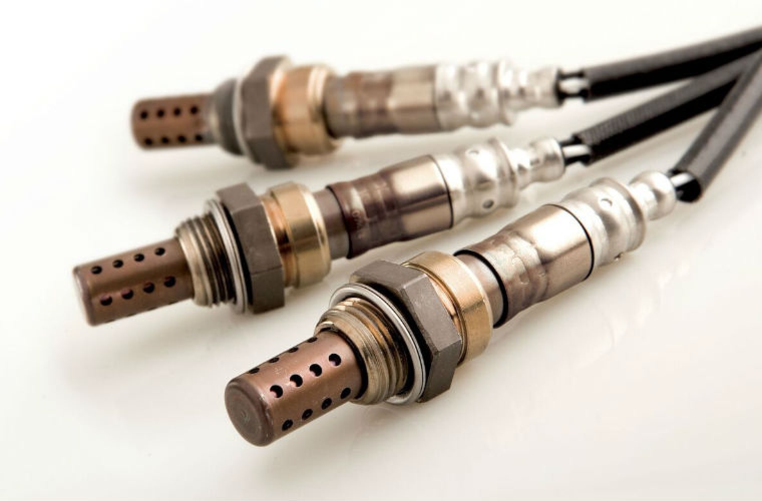
4 Wire Lambda Sensor Wiring Diagram is a crucial tool for mechanics and DIY enthusiasts alike when working on automotive electrical systems. These diagrams provide a detailed outline of how the wires should be connected to the lambda sensor, ensuring proper functionality.
Why are 4 Wire Lambda Sensor Wiring Diagrams essential?
4 Wire Lambda Sensor Wiring Diagrams are essential for several reasons:
- Ensure correct wiring connections
- Prevent electrical shorts or damage
- Maximize sensor performance
- Facilitate troubleshooting and repairs
How to read and interpret 4 Wire Lambda Sensor Wiring Diagrams effectively
Reading and interpreting 4 Wire Lambda Sensor Wiring Diagrams may seem daunting at first, but with practice, it becomes second nature. Here’s a simple guide:
- Identify the lambda sensor model and corresponding wiring diagram
- Understand the color-coding of wires for positive, negative, and signal connections
- Follow the diagram step-by-step to ensure correct wiring
- Double-check connections before powering up the system
How 4 Wire Lambda Sensor Wiring Diagrams are used for troubleshooting electrical problems
4 Wire Lambda Sensor Wiring Diagrams play a crucial role in troubleshooting electrical issues. By referencing the diagram, you can:
- Identify faulty connections or wiring issues
- Verify proper sensor installation
- Pinpoint areas of concern for further inspection
- Guide in replacing or repairing damaged components
Importance of safety when working with electrical systems
When working with electrical systems and wiring diagrams, safety should always be a top priority. Here are some safety tips and best practices:
- Disconnect the power source before working on any electrical components
- Use insulated tools to prevent electrical shocks
- Avoid working on wet surfaces to reduce the risk of electric shock
- Seek professional help if unsure about any electrical work
4 Wire Lambda Sensor Wiring Diagram
4 Wire Lambda Sensor Wiring Diagram – Greenist

4 Wire O2 Sensor Wiring Diagram Honda

Lambda LSU4.9 Sensor Control

OXYGEN SENSORS /LAMBDA SENSOR/: PARTS, TYPES, WORKING

How to install Universal Fit Lambda Sensors

What is Lambda Sensor? | How Lambda Oxygen Sensor Works? | Automobile

How to fit lambda sensors in six simple steps – Garagewire

Mk4 20v turbo lambda wires
