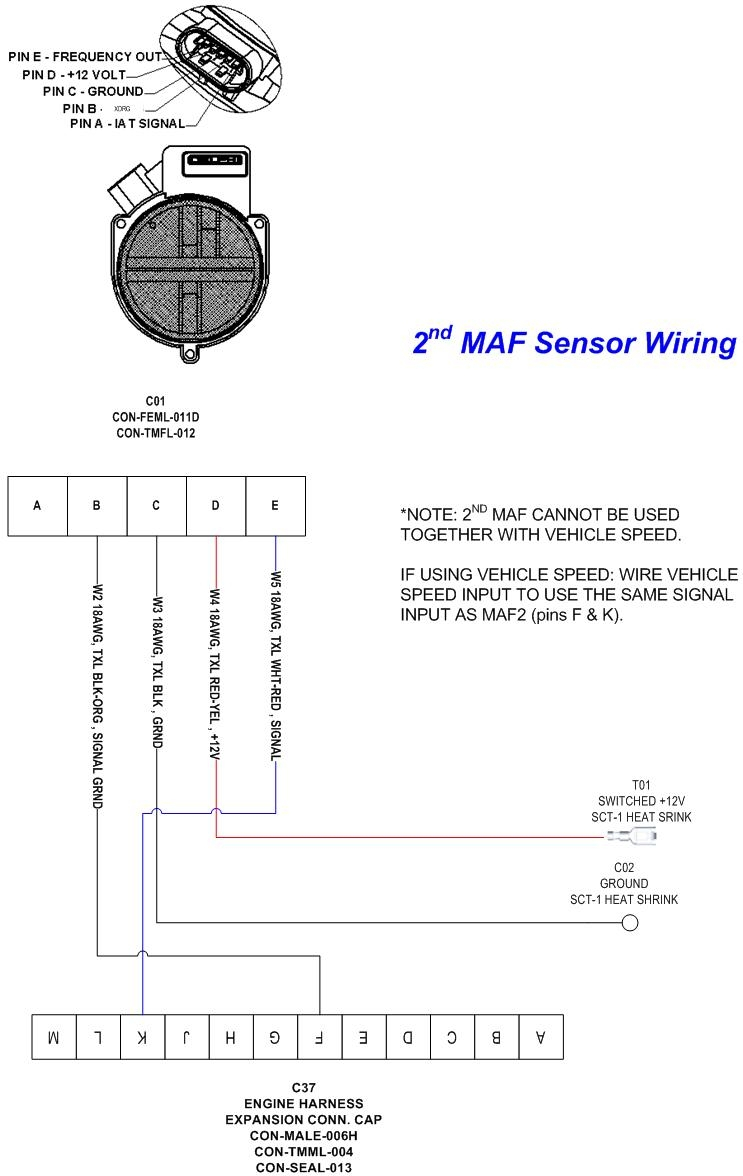
Are you looking for information on how to properly wire a 4 Pin Mass Air Flow Sensor? Look no further! In this article, we will provide you with a comprehensive guide on 4 Pin Mass Air Flow Sensor Wiring Diagram to help you understand its importance, how to read it effectively, and how it can be used for troubleshooting electrical problems.
Why are 4 Pin Mass Air Flow Sensor Wiring Diagrams Essential?
- 4 Pin Mass Air Flow Sensor Wiring Diagrams are essential for understanding the electrical connections and wiring configuration of the sensor.
- They help ensure the correct installation and proper functioning of the sensor.
- They provide a visual representation of the wiring layout, making it easier to identify and troubleshoot any potential issues.
How to Read and Interpret 4 Pin Mass Air Flow Sensor Wiring Diagrams Effectively
- Start by familiarizing yourself with the different components and symbols used in the diagram.
- Follow the lines and connections to understand how the various parts of the sensor are interconnected.
- Pay attention to the color codes and labels to identify the correct wires and connections.
Using 4 Pin Mass Air Flow Sensor Wiring Diagrams for Troubleshooting Electrical Problems
- 4 Pin Mass Air Flow Sensor Wiring Diagrams can be used to identify and resolve electrical issues such as faulty connections, shorts, or open circuits.
- By comparing the actual wiring with the diagram, you can pinpoint the source of the problem and make the necessary repairs.
- They can also help in diagnosing sensor malfunctions and determining if the sensor needs to be replaced.
Importance of Safety When Working with Electrical Systems
When working with electrical systems and using wiring diagrams, it is crucial to prioritize safety. Here are some tips and best practices to keep in mind:
- Always turn off the power source before working on any electrical wiring.
- Use insulated tools to prevent electric shock.
- Avoid working on wet surfaces or in damp conditions to reduce the risk of electrical hazards.
- If you are unsure or uncomfortable working with electrical systems, seek the help of a professional mechanic or electrician.
4 Pin Mass Air Flow Sensor Wiring Diagram
Mass Air Flow Sensor Wiring

Top 133+ images toyota maf sensor wiring diagram – In.thptnganamst.edu.vn

Repair Guides

4 Pin Maf Sensor Wiring Diagram – On a 2010 f 150 RAPTOR THE MASS AIR

Mass Air Flow Sensor Wiring Diagram – Diagram Stream

Engine Air Flow Diagram

1.6 tdi Mass Airflow Sensor wiring pinouts | VW TDI forum, Audi
4 Wire Maf Sensor Wiring Diagram – 4 wire to 3 wire MAF swap successful
