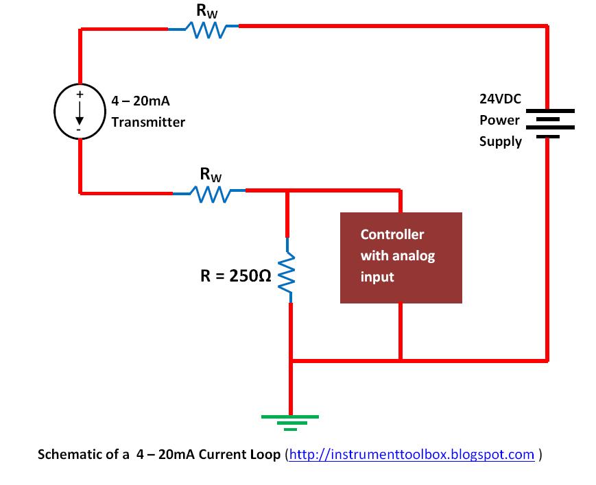
When it comes to understanding electrical systems, the 4 20ma Loop Powered Wiring Diagram is an essential tool that provides a visual representation of the wiring configuration for loop powered devices. This diagram helps technicians and engineers to troubleshoot, install, and maintain electrical systems efficiently. Let’s delve into the details of this important diagram.
Importance of 4 20ma Loop Powered Wiring Diagram
The 4 20ma Loop Powered Wiring Diagram is crucial for the following reasons:
- It shows the connection points of the loop powered devices, ensuring proper installation.
- It helps in identifying potential issues or faults in the wiring system.
- It serves as a guide for technicians to understand the electrical setup of the system.
Reading and Interpreting 4 20ma Loop Powered Wiring Diagram
Reading and interpreting the 4 20ma Loop Powered Wiring Diagram effectively requires attention to detail. Here are some tips to help you:
- Identify the power source and the loop powered devices on the diagram.
- Follow the flow of the wiring from the power source to the devices.
- Pay attention to the symbols and labels used in the diagram to understand the connections.
Using 4 20ma Loop Powered Wiring Diagram for Troubleshooting
When troubleshooting electrical problems, the 4 20ma Loop Powered Wiring Diagram can be a valuable asset. Here’s how you can use it effectively:
- Check for any loose connections or faulty wiring indicated in the diagram.
- Use a multimeter to test the continuity of the wires and ensure proper conductivity.
- Refer to the diagram to locate any potential short circuits or open circuits in the system.
Safety Tips for Working with 4 20ma Loop Powered Wiring Diagram
Working with electrical systems can be hazardous, so it’s essential to follow safety precautions when using wiring diagrams:
- Always disconnect the power source before working on any electrical system.
- Use insulated tools to prevent electrical shocks.
- Wear appropriate personal protective equipment, such as gloves and safety goggles.
4 20ma Loop Powered Wiring Diagram
Basics of The 4 – 20mA Current Loop ~ Learning Instrumentation And

4-20 mA Current Loop | Basic Fundamentals

How a 4-20 mA Transmitter Works? – Instrumentation Tools

How a 4-20mA Current Loop Works | Sierra Instruments | Sierra Instruments

4-20ma Loop Powered Wiring Diagram

4 20Ma Loop Powered Wiring Diagram – Knittystash.com

4 to 20 mA current loops made easy

How to connect 4- 20 mA transmitters – Current Loop Power for { Source
