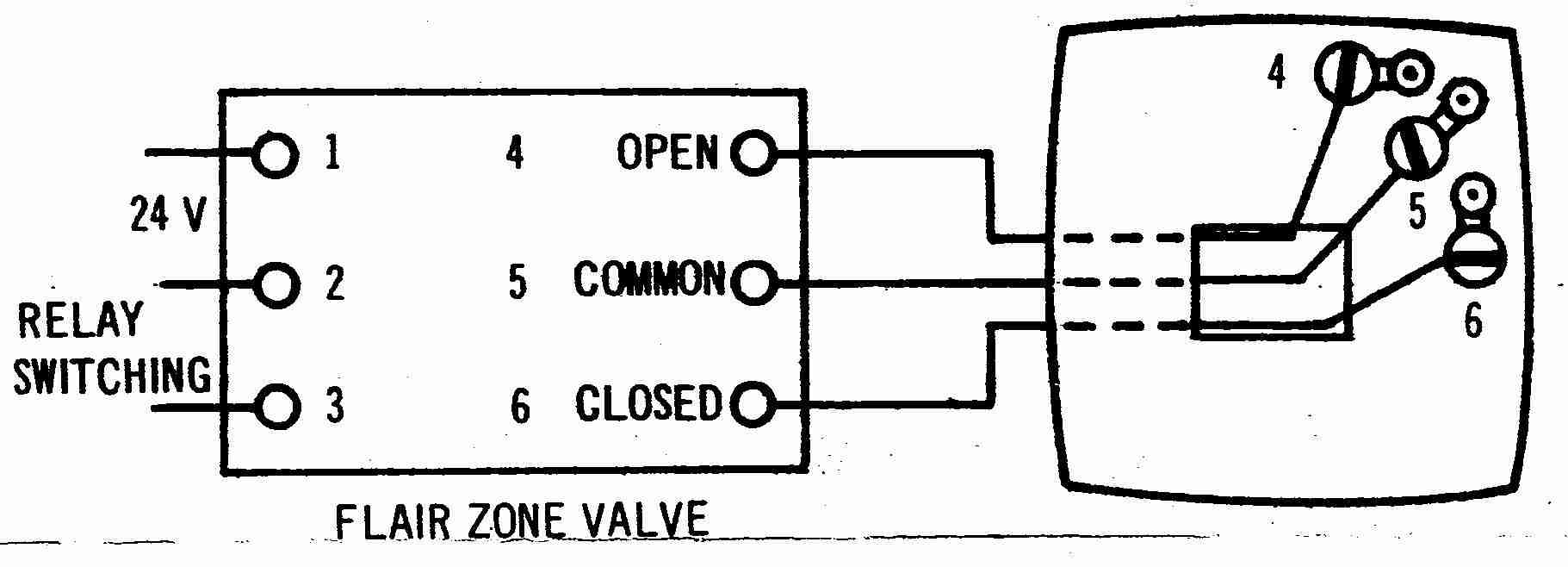
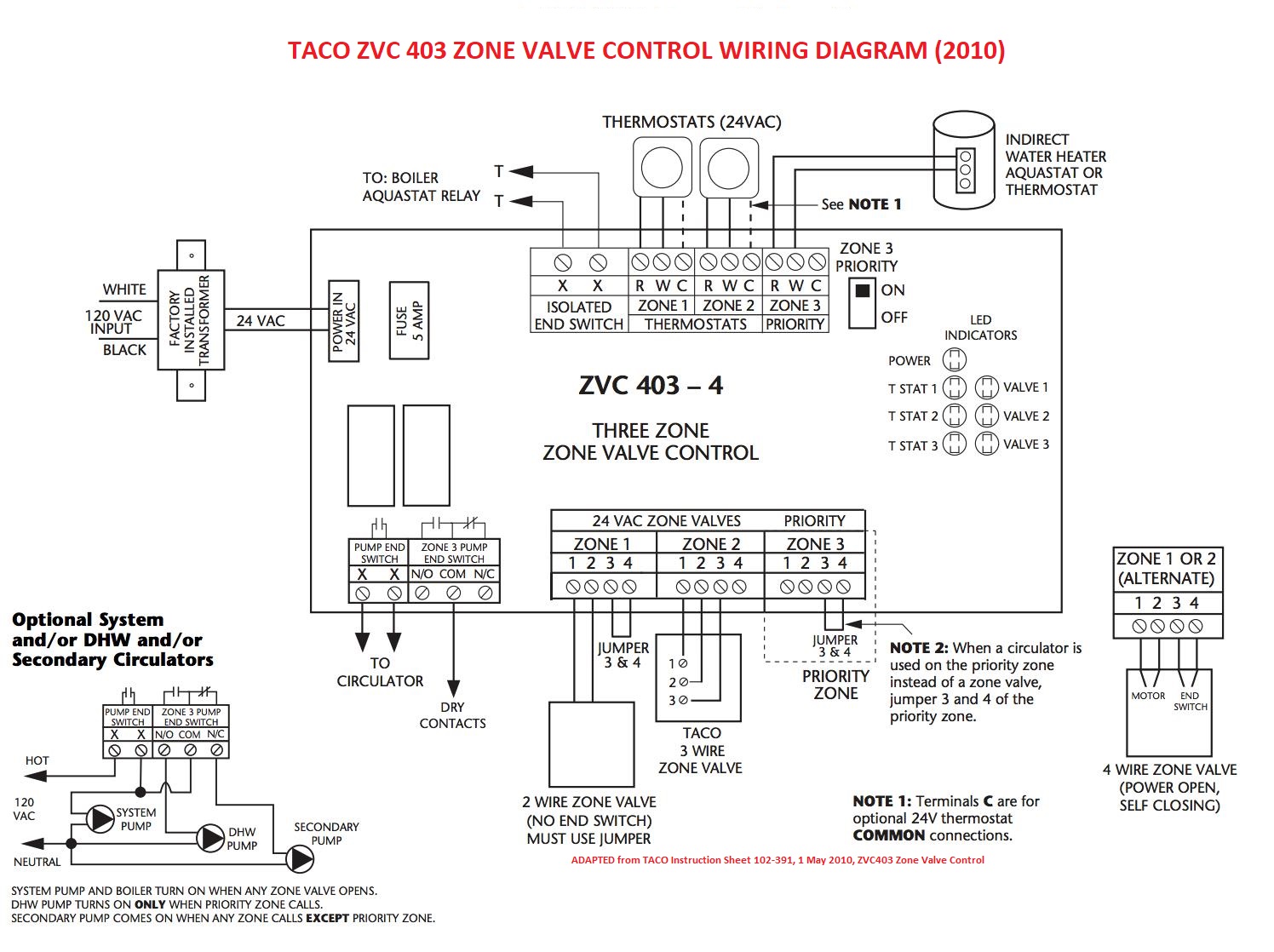
Are you looking to understand how a 3 wire zone valve wiring diagram works? This diagram is a crucial tool for anyone working with heating systems that use zone valves. It provides a visual representation of the electrical connections required to operate the zone valve efficiently. Let’s delve into the details of how to read, interpret, and use a 3 wire zone valve wiring diagram effectively.
Importance of 3 Wire Zone Valve Wiring Diagram
Understanding a 3 wire zone valve wiring diagram is essential for the following reasons:
- Ensures proper installation of the zone valve
- Helps in troubleshooting electrical issues
- Ensures safety during maintenance and repairs
Reading and Interpreting 3 Wire Zone Valve Wiring Diagram
When looking at a 3 wire zone valve wiring diagram, pay attention to the following key components:
- Power supply connections
- Thermostat connections
- Zone valve connections
- Transformer connections
Using 3 Wire Zone Valve Wiring Diagram for Troubleshooting
When troubleshooting electrical problems in a heating system with zone valves, the wiring diagram can be a valuable resource. Follow these steps:
- Identify the problem area on the diagram
- Trace the electrical connections related to the issue
- Check for loose connections or damaged wires
- Refer to the diagram for correct voltage and resistance values
Safety Tips for Working with 3 Wire Zone Valve Wiring Diagram
Working with electrical systems can be dangerous if proper precautions are not taken. Follow these safety tips when using a wiring diagram:
- Always turn off the power supply before working on the system
- Use insulated tools to avoid electrical shocks
- Wear protective gear such as gloves and goggles
- Double-check all connections before restoring power
3 Wire Zone Valve Wiring Diagram
Zone Valve Wiring Installation & Instructions: Guide to heating system

Zone Valve Wiring Manuals Installation & Instructions: Guide to heating

Honeywell V8043e Zone Valve Wiring Diagram – IOT Wiring Diagram

Zone Valve Wiring Installation & Instructions: Guide to heating system

Taco 3 Wire Zone Valve Wiring Diagram

Three Wire Zone Valve Wiring – Wiring Diagrams Hubs – Honeywell Zone

Honeywell V8043 Zone Valve Wiring Diagram – Wiring Diagram

White Rodgers 3 Wire Zone Valve Wiring Diagram
