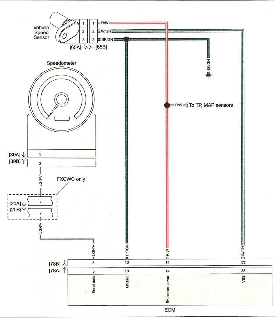
When it comes to understanding the intricacies of a vehicle’s electrical system, a 3 Wire Speed Sensor Wiring Diagram can be a valuable tool. This diagram provides a visual representation of how the speed sensor is wired into the vehicle’s electrical system, helping mechanics and enthusiasts alike navigate the complexities of modern automotive technology.
Why are 3 Wire Speed Sensor Wiring Diagrams Essential?
A 3 Wire Speed Sensor Wiring Diagram is essential for several reasons:
- Ensures proper installation of the speed sensor
- Aids in troubleshooting electrical issues related to the speed sensor
- Helps in understanding the relationship between the speed sensor and other components in the vehicle
Reading and Interpreting 3 Wire Speed Sensor Wiring Diagrams
Reading and interpreting a 3 Wire Speed Sensor Wiring Diagram may seem daunting at first, but with a little practice, it can become second nature. Here are some tips to help you effectively read and interpret these diagrams:
- Understand the symbols and color codes used in the diagram
- Follow the flow of the wiring from one component to another
- Pay attention to the connections and terminals indicated in the diagram
Using 3 Wire Speed Sensor Wiring Diagrams for Troubleshooting
3 Wire Speed Sensor Wiring Diagrams are invaluable tools when it comes to troubleshooting electrical problems in a vehicle. By referencing the diagram, you can:
- Identify potential issues with the speed sensor wiring
- Locate faulty connections or damaged wires
- Verify proper voltage and continuity in the circuit
Importance of Safety
When working with electrical systems and using wiring diagrams, safety should always be a top priority. Here are some safety tips and best practices to keep in mind:
- Always disconnect the battery before working on any electrical components
- Use insulated tools to avoid the risk of electric shock
- Avoid working on electrical systems in wet or damp conditions
- Double-check all connections before reapplying power to the system
3 Wire Speed Sensor Wiring Diagram
3 Wire Speed Sensor Wiring Diagram: A Comprehensive Guide – Moo Wiring
3 Wire Speed Sensor Wiring Diagram

Honda speed sensor wiring diagram

3 Wire Speed Sensor Wiring Diagram: A Comprehensive Guide – Moo Wiring
3 Wire Speed Sensor Diagram – General Wiring Diagram

3 wire Digital Speedometer Sensor – Modern Driveline

[DIAGRAM] 3 Speed Sensor Wire Diagram – MYDIAGRAM.ONLINE
![3 Wire Speed Sensor Wiring Diagram [DIAGRAM] 3 Speed Sensor Wire Diagram - MYDIAGRAM.ONLINE](https://i1.wp.com/troubleshootmyvehicle.com/images/articles-600-699/610/614/image_1.gif)
3 Wire Speed Sensor Wiring Diagram: A Comprehensive Guide – Moo Wiring
