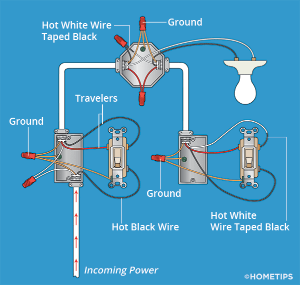
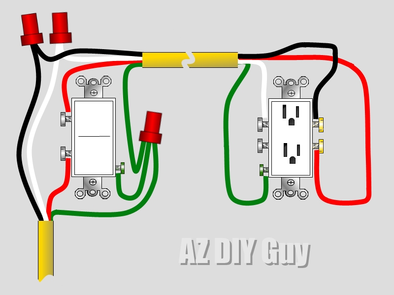
Are you looking to understand how a 3 Way Switched Outlet Wiring Diagram works? This diagram is essential for anyone looking to wire a three-way switch to control an outlet or a light fixture. It shows the electrical connections between the switches and the outlet, allowing you to control the power flow from multiple locations.
Why 3 Way Switched Outlet Wiring Diagrams are essential:
- Provide a clear visual representation of the electrical connections
- Help ensure proper wiring and prevent electrical hazards
- Allow for control of an outlet or light fixture from multiple locations
How to read and interpret 3 Way Switched Outlet Wiring Diagrams:
When looking at a 3 Way Switched Outlet Wiring Diagram, it’s important to understand the symbols and connections used. The diagram will typically show the wiring between the switches, the outlet, and the power source. Pay attention to the color codes and labels to ensure the correct connections are made.
Using 3 Way Switched Outlet Wiring Diagrams for troubleshooting:
3 Way Switched Outlet Wiring Diagrams can be a valuable tool when troubleshooting electrical problems. By following the diagram, you can easily identify any faulty connections or components that may be causing issues. This can save time and effort when trying to diagnose and fix electrical problems.
Importance of safety when working with electrical systems:
- Always turn off the power before working on any electrical wiring
- Use insulated tools to prevent electric shock
- Double-check all connections before turning the power back on
- Consult a professional electrician if you are unsure about any aspect of the wiring process
3 Way Switched Outlet Wiring Diagram
3 Way Switched Outlet Wiring Diagram / Wiring Diagram For 3 Way Switch
How to Wire Three-Way Light Switches | HomeTips

How To Wire A 3 Way Switch With Multiple Outlets | dont wiring without us

A Guide To 3-Way Switch Wiring Diagram With Outlet – Wiring Diagram

An Electrician Explains How to Wire a Switched (Half-Hot) Outlet

Basic 3 Way Switch Wiring – 3 Way Switch Wiring Diagram & Schematic

3 Way Switch Receptacle Wiring Diagram

How To: Wire a Split, Switched Outlet by AZ DIY Guy's Projects | Bob
