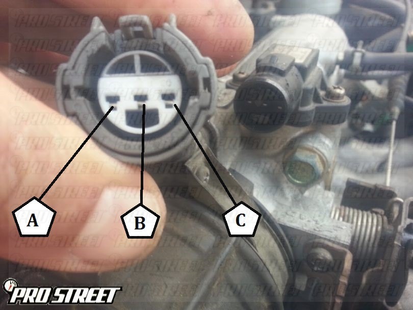
When it comes to understanding the intricacies of your vehicle’s electrical system, having a grasp on the 3 Pin Map Sensor Wiring Diagram is essential. This diagram provides a detailed outline of how the map sensor is wired within your vehicle, allowing you to troubleshoot electrical issues effectively.
Why are 3 Pin Map Sensor Wiring Diagrams Essential?
1. They provide a visual representation of the wiring connections for the map sensor.
2. They help in identifying any potential issues with the wiring that may be causing problems in the sensor’s functionality.
3. They serve as a guide for proper installation and maintenance of the map sensor.
How to Read and Interpret 3 Pin Map Sensor Wiring Diagrams Effectively
1. Start by identifying the pins on the map sensor and corresponding wires in the diagram.
2. Follow the wiring path from the sensor to the electrical control unit (ECU) or other components.
3. Pay attention to the color-coding of the wires to ensure correct connections.
Using 3 Pin Map Sensor Wiring Diagrams for Troubleshooting Electrical Problems
1. Check for continuity between the sensor pins and the ECU to ensure a proper connection.
2. Look for any signs of damage or wear on the wiring that may be affecting the sensor’s performance.
3. Compare the diagram with the actual wiring in your vehicle to spot any discrepancies that could be causing issues.
Importance of Safety When Working with Electrical Systems
1. Always disconnect the battery before working on any electrical components to prevent the risk of electric shock.
2. Use insulated tools to avoid short circuits or accidental contact with live wires.
3. Double-check your connections and wiring before reassembling components to ensure everything is correctly in place.
By understanding how to read and interpret 3 Pin Map Sensor Wiring Diagrams, you can effectively troubleshoot electrical issues in your vehicle while prioritizing safety throughout the process.
3 Pin Map Sensor Wiring Diagram
Map Sensor Wiring Diagram

bosch map sensor pinout – Wiring Digital and Schematic

Map Sensor Wiring Diagram
Where is the MAP sensor on a 2004 Chevy Tahoe and what wire goes to the

DTC P0108 – How To Service Acura Integra MAP Sensor

Map Sensor Wiring Diagram Engine – Wiring Diagram

Wiring for AEM map sensor and AIT | Ford Mustang Forums
A Comprehensive Guide To Map Sensor Wiring Diagram – Moo Wiring
