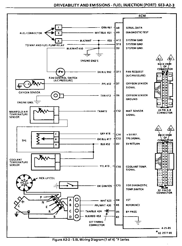
When it comes to understanding the electrical components of a vehicle, the 2 Wire Temp Sensor Wiring Diagram is a crucial tool. This diagram provides a visual representation of how the two wires of a temperature sensor are connected to the vehicle’s electrical system. By following this diagram, mechanics and DIY enthusiasts can ensure proper installation and troubleshooting of temperature sensors.
Why are 2 Wire Temp Sensor Wiring Diagrams Essential?
2 Wire Temp Sensor Wiring Diagrams are essential for several reasons:
- They provide a clear visual guide on how the temperature sensor wires should be connected.
- They help prevent incorrect wiring that can lead to sensor malfunctions or damage.
- They ensure proper communication between the sensor and the vehicle’s computer system.
How to Read and Interpret 2 Wire Temp Sensor Wiring Diagrams Effectively
Reading and interpreting 2 Wire Temp Sensor Wiring Diagrams can be made easier by following these steps:
- Identify the two wires coming from the temperature sensor.
- Locate the corresponding terminals or connectors on the vehicle’s wiring harness.
- Match the wire colors or labels on the diagram to the actual wires in the vehicle.
- Follow the diagram to ensure the correct connections are made.
Using 2 Wire Temp Sensor Wiring Diagrams for Troubleshooting Electrical Problems
2 Wire Temp Sensor Wiring Diagrams can be invaluable when troubleshooting electrical problems related to temperature sensors. Mechanics can use these diagrams to:
- Verify proper sensor connections.
- Check for continuity and resistance in the sensor circuit.
- Identify potential wiring issues that may be causing sensor malfunctions.
Importance of Safety When Working with Electrical Systems
It is important to prioritize safety when working with electrical systems and using wiring diagrams. Here are some safety tips and best practices to keep in mind:
- Always disconnect the vehicle’s battery before working on any electrical components.
- Use insulated tools to prevent electrical shock.
- Avoid working on electrical systems in wet or damp conditions.
- Double-check all connections before powering up the vehicle.
2 Wire Temp Sensor Wiring Diagram
2 Wire Temp Sensor Wiring Diagram

2 Wire Temp Sensor Coolant Temperature Sensor Wiring Diagram – inspirenetic

1, 2 & 3 Wire Coolant Temperature Sensor Wiring Diagram

2 Wire Temp Sensor Wiring Diagram

Electric Temperature Gauge Wiring Diagram – Wiring Diagram

2 Wire Temp Sensor Wiring Diagram

2 Wire Temp Sensor Wiring Diagram

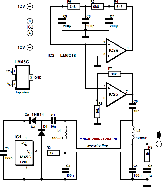
Two-Wire Temperature Sensor Circuit Diagram
