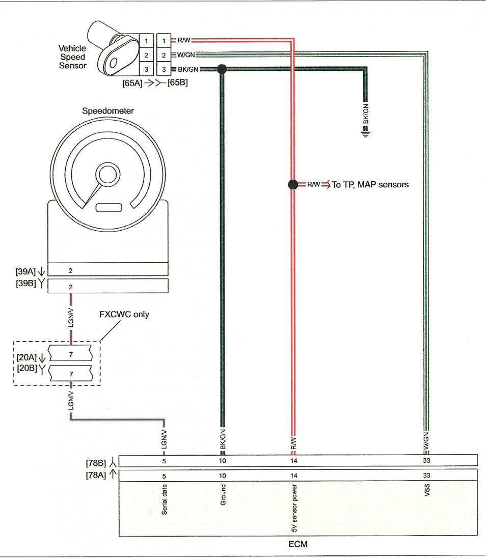
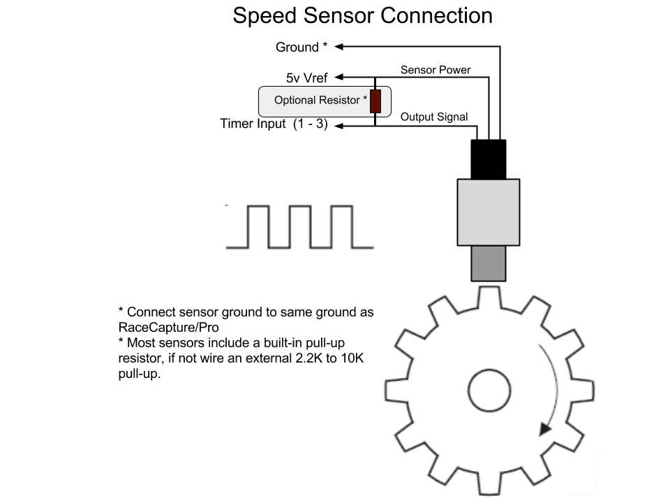
2 Wire Speed Sensor Wiring Diagrams are essential tools for understanding the electrical connections of a speed sensor in a vehicle or machinery. These diagrams provide a visual representation of the wiring layout, helping mechanics and technicians troubleshoot issues, make repairs, or install new components.
Importance of 2 Wire Speed Sensor Wiring Diagrams
Here are a few reasons why these wiring diagrams are crucial:
- Help in identifying the correct wires and their connections
- Assist in diagnosing electrical issues related to the speed sensor
- Ensure proper installation of new speed sensor components
Reading and Interpreting 2 Wire Speed Sensor Wiring Diagrams
Reading and interpreting wiring diagrams can be daunting for some, but with the right approach, it becomes easier:
- Start by understanding the symbols and color codes used in the diagram
- Follow the wiring paths and connections to identify the components involved
- Refer to the legend or key if you’re unsure about any symbol or abbreviation
Using 2 Wire Speed Sensor Wiring Diagrams for Troubleshooting
When faced with electrical problems related to the speed sensor, these diagrams can be a lifesaver:
- Check for continuity in the wiring to pinpoint any breaks or loose connections
- Verify the voltage levels at different points to ensure proper power supply
- Compare the actual wiring with the diagram to spot any discrepancies
Safety Tips for Working with Electrical Systems
Working with electrical systems can be dangerous if proper precautions are not taken. Here are some safety tips to keep in mind:
- Always disconnect the power source before working on any electrical component
- Use insulated tools to prevent electrical shocks
- Avoid working on wet surfaces or in damp environments
- Double-check your connections before turning the power back on
2 Wire Speed Sensor Wiring Diagram
Two Wire Sensor Working Principle and Animation

Honda speed sensor wiring diagram

2 wire speed sensor wiring diagram 700r4 transmission speed sensor

Tool Briefing: Can Bus Communication Failure – 2 Wire Speed Sensor

2 Wire Speed Sensor Wiring Diagram – Wiring Diagram

Speed Sensor Wiring Diagram

2 Wire Speed Sensor Wiring Diagram – DiagramInfo

Abs Sensor 2 Wire Speed Sensor Wiring Diagram Collection
