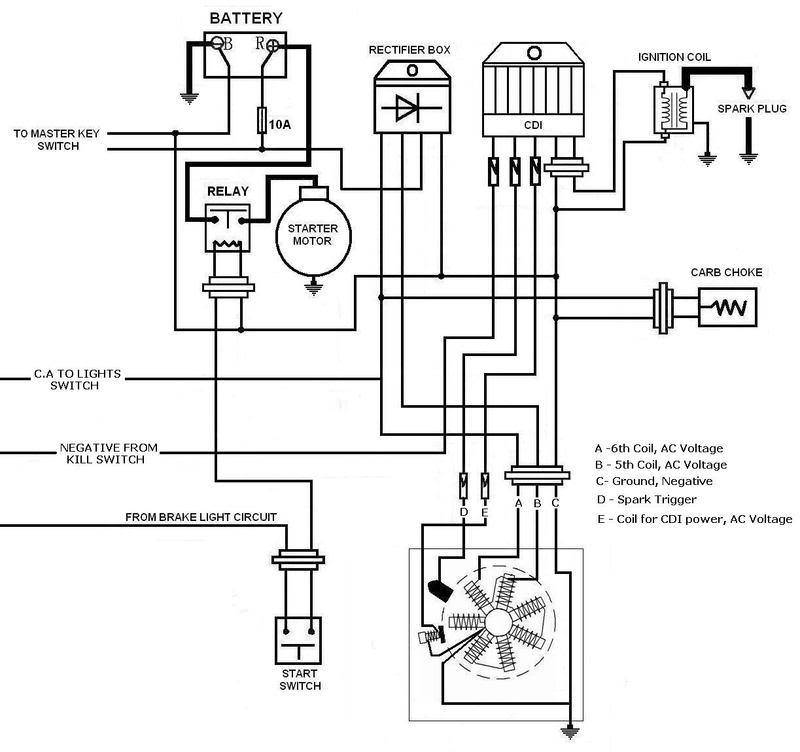
2 Stroke Cdi Wiring Diagrams are essential tools for understanding the electrical systems in 2-stroke engines. These diagrams provide a visual representation of the wiring and connections between the CDI unit, ignition coil, spark plug, and other components in the system. By studying these diagrams, mechanics can troubleshoot electrical issues, make repairs, and ensure that the engine is running smoothly.
Importance of 2 Stroke Cdi Wiring Diagrams
- Help understand the electrical system of the engine
- Aid in troubleshooting electrical problems
- Ensure proper connections and wiring
- Assist in making repairs and modifications
Reading and Interpreting 2 Stroke Cdi Wiring Diagrams
When looking at a 2 Stroke Cdi Wiring Diagram, it’s important to understand the symbols and color codes used to represent different components and connections. Pay attention to the key provided in the diagram to identify each part and its function. Follow the lines and arrows to trace the flow of electricity through the system and locate any potential issues.
Using 2 Stroke Cdi Wiring Diagrams for Troubleshooting
2 Stroke Cdi Wiring Diagrams are invaluable for diagnosing and fixing electrical problems in 2-stroke engines. By comparing the actual wiring in the engine with the diagram, mechanics can identify faulty connections, damaged wires, or malfunctioning components. This information is crucial for ensuring that the engine runs smoothly and reliably.
Safety Tips for Working with Electrical Systems
- Always wear insulated gloves and eye protection when working with electrical systems
- Disconnect the battery or power source before making any repairs or modifications
- Avoid touching exposed wires or components while the engine is running
- Use a multimeter to test connections and ensure proper voltage levels
- If unsure of any wiring or connections, consult a professional mechanic or electrician
2 Stroke Cdi Wiring Diagram
2 Stroke Cdi Wiring Diagram

2 STROKE RACE CDI IGNITION JOG Minarelli 1E40QMB 9 CD10

2 Stroke Johnson Outboard Wiring Diagram Pdf – Wiring Diagram and

2 Stroke Cdi Wiring Diagram

How To Wire A Cdi Box
Bajaj 2 Stroke 3 Wheeler Wiring Diagram – Chicic

2 Stroke Cdi Wiring Diagram

Cdi Wiring Diagram – Wiring Diagram
