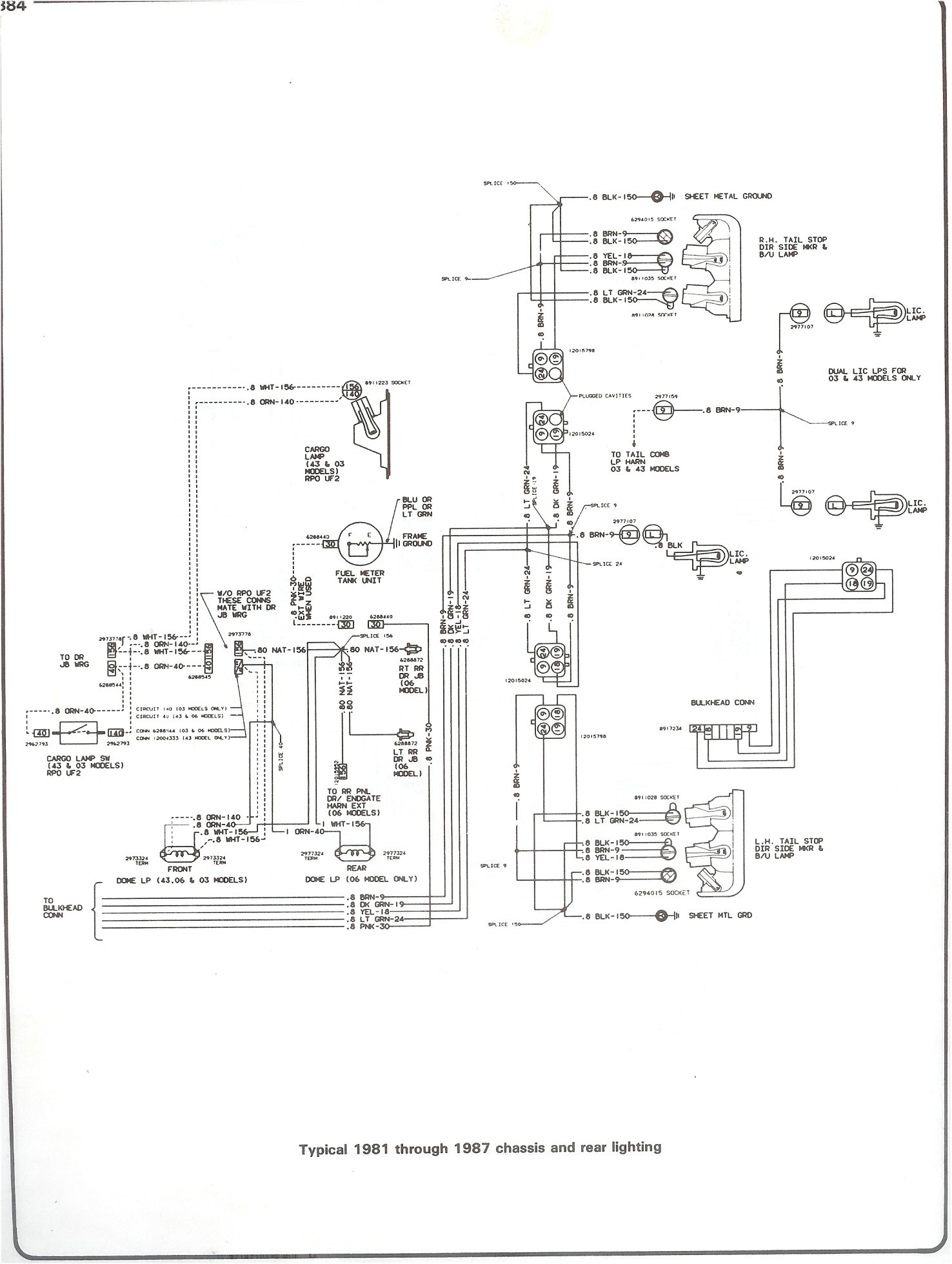
When dealing with vintage vehicles like the 1970 C10, understanding the ignition switch wiring diagram is crucial for proper maintenance and repairs. The ignition switch wiring diagram provides a detailed outline of how the electrical system in the vehicle is connected, ensuring that all components work together seamlessly.
Why are 1970 C10 Ignition Switch Wiring Diagrams Essential?
Understanding the ignition switch wiring diagram for your 1970 C10 is essential for the following reasons:
- Ensures proper connection of electrical components
- Aids in diagnosing and troubleshooting electrical issues
- Helps in installing aftermarket accessories or upgrades
How to Read and Interpret 1970 C10 Ignition Switch Wiring Diagrams
Reading and interpreting the ignition switch wiring diagram can seem daunting at first, but with some guidance, it becomes easier:
- Identify key components such as the ignition switch, starter, battery, and other electrical components
- Follow the lines to see how each component is connected
- Refer to the color codes and symbols to understand the wiring connections
Using 1970 C10 Ignition Switch Wiring Diagrams for Troubleshooting
The ignition switch wiring diagram is a valuable tool when troubleshooting electrical problems in your 1970 C10:
- Identify any loose or disconnected wires
- Check for continuity and voltage at different points in the wiring diagram
- Refer to the diagram to locate potential sources of the issue
Importance of Safety
When working with electrical systems and using wiring diagrams, safety should always be a top priority. Here are some safety tips and best practices to follow:
- Disconnect the battery before working on any electrical components
- Use insulated tools to prevent electrical shock
- Avoid working on the electrical system in wet conditions
- Double-check all connections before reassembling components
1970 C10 Ignition Switch Wiring Diagram
1970 C10 Chevy Truck Wiring Diagram

1970 C10 Ignition Switch Wiring Diagram – Collection – Faceitsalon.com
Chevy Ignition Switch Wiring Diagram 1950, 70, 80, 90 – 2000

C10 Ignition Switch Wiring

1970 c10 ignition switch wiring diagram information | desbennettconsultants

1970 Chevy C10 Wiring Diagram

1970 C10 Ignition Switch Wiring Diagram – Esquilo.io
1970 C10 Ignition Switch Wiring Diagram – Collection – Faceitsalon.com
