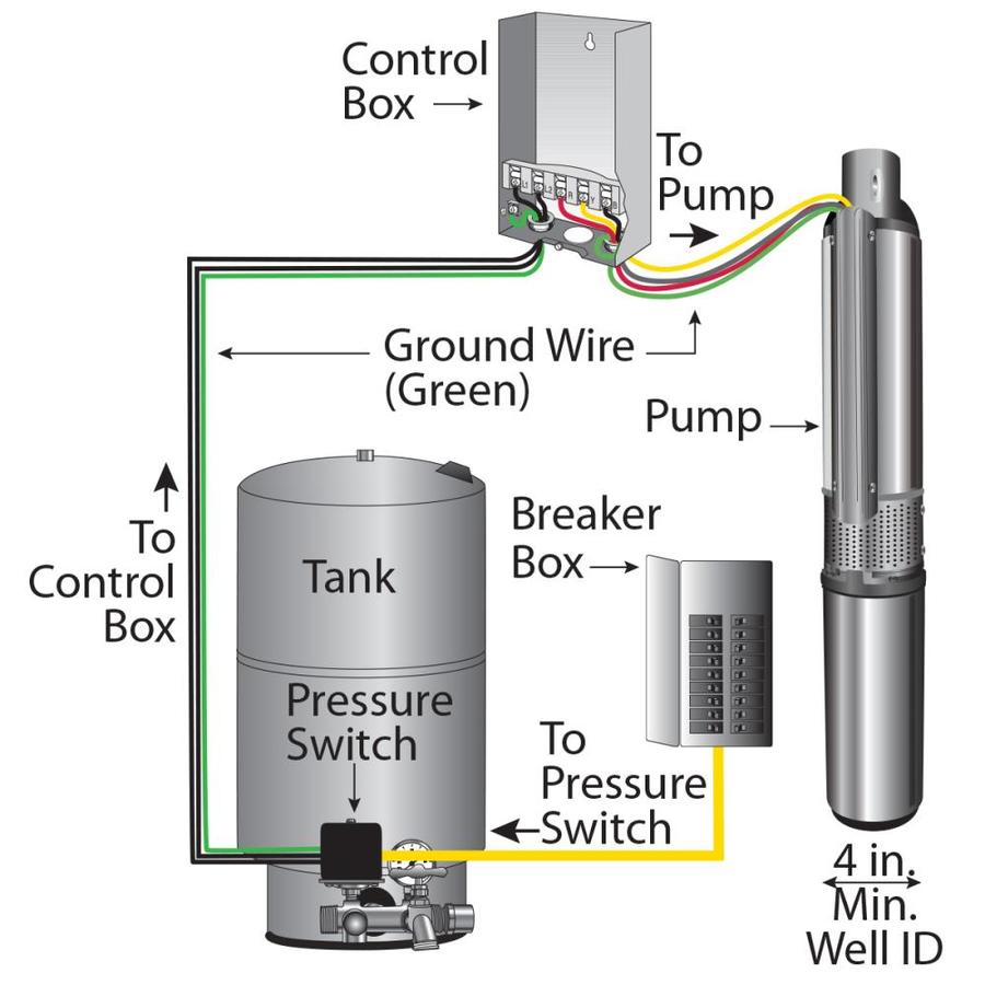
When it comes to ensuring the proper functioning of a well pump, having a thorough understanding of the 110 Volt Well Pump Wiring Diagram is crucial. This diagram serves as a roadmap for connecting the various components of the pump system and is essential for troubleshooting any electrical issues that may arise.
Why are 110 Volt Well Pump Wiring Diagrams Essential?
Understanding 110 Volt Well Pump Wiring Diagrams is essential for a variety of reasons:
- Ensuring proper installation of the well pump system
- Facilitating troubleshooting of electrical issues
- Preventing damage to the pump or other components
How to Read and Interpret 110 Volt Well Pump Wiring Diagrams
Interpreting a 110 Volt Well Pump Wiring Diagram may seem daunting at first, but with some guidance, it can become much easier:
- Identify the components of the system and their corresponding symbols
- Follow the flow of electricity through the diagram to understand the circuit
- Pay attention to color codes and labeling to ensure proper connections
Using 110 Volt Well Pump Wiring Diagrams for Troubleshooting
When faced with electrical problems in a well pump system, the Wiring Diagram can be a valuable tool:
- Identify any faulty connections or components
- Check for continuity and proper voltage levels at various points in the circuit
- Refer to the diagram to make necessary repairs or replacements
Safety Tips for Working with Electrical Systems
Working with electrical systems can be dangerous, so it’s important to prioritize safety:
- Always turn off the power before working on any electrical components
- Use insulated tools and wear protective gear to prevent shocks
- Ensure proper grounding and wiring connections to avoid short circuits
110 Volt Well Pump Wiring Diagram
110 Volt Well Pump Wiring Diagram – Plumbingpoints

Well Pump Motor Wiring Diagram – Sustainablemed

110 Volt Well Pump Wiring Diagram

Wiring Of Flotec Well Pump Diagram : Submersible Well Pump Wiring

110 volt well pump wiring diagram – Zen Lace
⭐ 110 Volt 3 Wire Submersible Pump Wiring Diagram ⭐ – Boderless creations

Wiring Well Pumps

Zoeller Pump Switch Wiring Diagram – Zoeller Submersible Sump Pump 1 Hp
