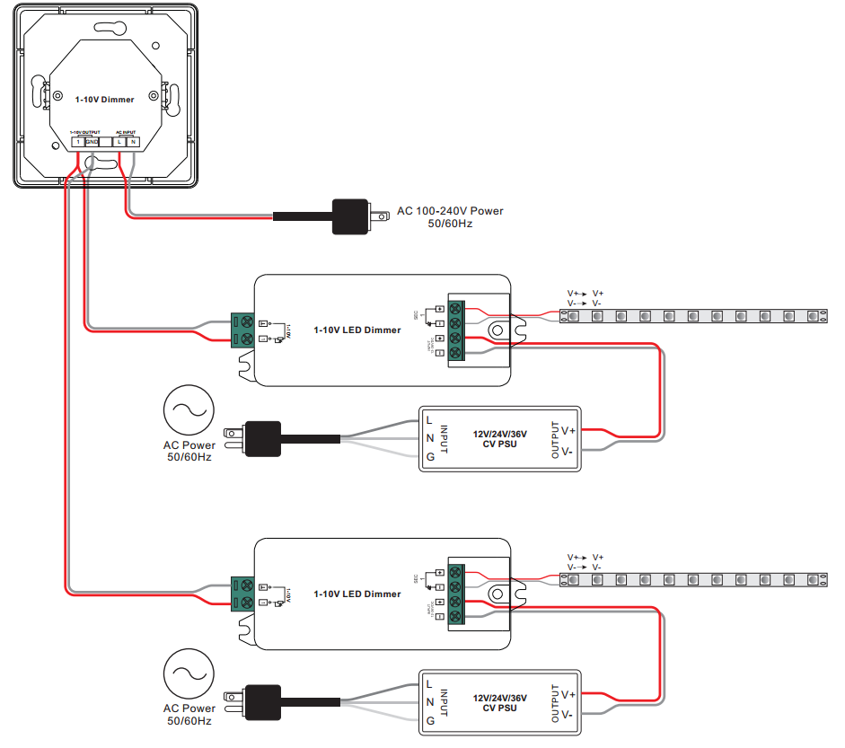
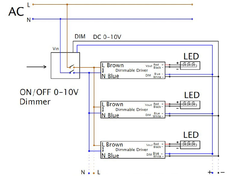
0 To 10 Volt Dimmer Wiring Diagrams are crucial tools for electricians and technicians working with lighting control systems. These diagrams provide a visual representation of the wiring connections and components involved in the installation of 0-10V dimmers, helping ensure a smooth and efficient installation process.
Importance of 0 To 10 Volt Dimmer Wiring Diagrams
- Ensure proper connection of wires and components
- Avoid potential errors or mistakes during installation
- Help troubleshoot issues effectively
- Ensure compliance with electrical codes and safety standards
Reading and Interpreting 0 To 10 Volt Dimmer Wiring Diagrams
When reading a 0 To 10 Volt Dimmer Wiring Diagram, it is essential to pay attention to the following key components:
- Input power source
- Dimmer switch or control module
- Dimmable LED driver or ballast
- Output to the lighting fixture
Using 0 To 10 Volt Dimmer Wiring Diagrams for Troubleshooting
0 To 10 Volt Dimmer Wiring Diagrams can be invaluable tools when troubleshooting electrical problems. By following the wiring diagram and tracing the connections, technicians can identify and resolve issues such as loose connections, faulty components, or wiring errors.
Safety Considerations
Working with electrical systems can be hazardous, so it is crucial to observe safety precautions when using wiring diagrams:
- Always turn off the power supply before working on any electrical connections
- Use insulated tools to avoid electric shocks
- Double-check all connections before energizing the circuit
- Wear appropriate personal protective equipment, such as gloves and safety glasses
0 To 10 Volt Dimmer Wiring Diagram
0 10v Dimmer Wiring Diagram – inspirearc

CV 0-10V Dimming LED Driver – Smart Home – Yoswit.com

[DIAGRAM] 0 10v Led Dimmer Circuit Diagram – MYDIAGRAM.ONLINE
![0 To 10 Volt Dimmer Wiring Diagram [DIAGRAM] 0 10v Led Dimmer Circuit Diagram - MYDIAGRAM.ONLINE](https://i1.wp.com/faceitsalon.com/wp-content/uploads/2018/07/lutron-diva-cl-wiring-diagram-led-dimming-wiring-diagram-0-10v-lutron-dimmer-14h.jpg)
0-10 Volt Dimming Wiring Diagram – Wiring Diagram Pictures

0 10v Dimmer Schematic

Dimmer 0-10 Volt Wiring Diagram

0 10 Volt Dimming Wiring Diagram – Cadician's Blog
